All FYP2 participants need to present their final year project on 24th April. The Industry Day start from 9:00 am to 2:00pm and will be held at Dewan Gemilang. The presentation was going smoothly but unfortunately, a tripping happen where some of the FYP project damaged due too many load. As the tripping happened, my GSM stop working due to short circuit. Luckily, all the part except the GSM module working perfectly fine.
Sunday, April 28, 2019

Week 10: Poster making
After finish the prototype, all FYP2 presenter need to design their poster for their project. The poster need to display all the information about the project.


Figure 10: FYP 2 Poster
Week 9: The result
Here's the result for the project
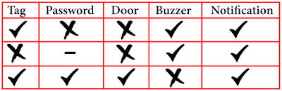


Table 9: Result

Sending 'open' message to open the door

If wrong password or tag detected by the system, it will send notification to owner phone.
Saturday, April 27, 2019
Wek 8: The prototype
After completing the housing, full coding is burn into the Arduino to see whether the prototype is working or not.


Final prototype
The coding
#include <MFRC522.h>
#include <LiquidCrystal_I2C.h>
#include <Keypad.h>
#include <SoftwareSerial.h>
#include <Servo.h>
#include <SPI.h>

// Create instances
SoftwareSerial SIM900(3, 4); // SoftwareSerial SIM900(Rx, Tx)
MFRC522 mfrc522(10, 9); // MFRC522 mfrc522(SS_PIN, RST_PIN)
LiquidCrystal_I2C lcd(0x27, 16, 2);
Servo sg90;

// Initialize Pins for led's, servo and buzzer
// Blue LED is connected to 5V
constexpr uint8_t greenLed = 7;
constexpr uint8_t redLed = 6;
constexpr uint8_t servoPin = 8;
constexpr uint8_t buzzerPin = 5;

char initial_password[4] = {'1', '2', '3', '4'};  // Variable to store initial password
String tagUID = "aa bb cc dd";  // String to store UID of tag. Change it with your tag's UID
char password[4];   // Variable to store users password
boolean RFIDMode = true; // boolean to change modes
boolean NormalMode = true; // boolean to change modes
char key_pressed = 0; // Variable to store incoming keys
uint8_t i = 0;  // Variable used for counter

// defining how many rows and columns our keypad have
const byte rows = 4;
const byte columns = 4;

// Keypad pin map
char hexaKeys[rows][columns] = {
  {'1', '2', '3', 'A'},
  {'4', '5', '6', 'B'},
  {'7', '8', '9', 'C'},
  {'*', '0', '#', 'D'}
};

// Initializing pins for keypad
byte row_pins[rows] = {A0, A1, A2, A3};
byte column_pins[columns] = {2, 1, 0};

// Create instance for keypad
Keypad keypad_key = Keypad( makeKeymap(hexaKeys), row_pins, column_pins, rows, columns);

void setup() {
  // Arduino Pin configuration
  pinMode(buzzerPin, OUTPUT);
  pinMode(redLed, OUTPUT);
  pinMode(greenLed, OUTPUT);

  sg90.attach(servoPin);  //Declare pin 8 for servo
  sg90.write(0); // Set initial position at 0 degrees

  lcd.begin();   // LCD screen
  lcd.backlight();
  SPI.begin();      // Init SPI bus
  mfrc522.PCD_Init();   // Init MFRC522

  // Arduino communicates with SIM900 GSM shield at a baud rate of 19200
  // Make sure that corresponds to the baud rate of your module
  SIM900.begin(19200);

  // AT command to set SIM900 to SMS mode
  SIM900.print("AT+CMGF=1\r");
  delay(100);
  // Set module to send SMS data to serial out upon receipt
  SIM900.print("AT+CNMI=2,2,0,0,0\r");
  delay(100);

  lcd.clear(); // Clear LCD screen
}

void loop() {
  if (NormalMode == false) {
    // Function to receive message
    receive_message();
  }

  else if (NormalMode == true) {
    // System will first look for mode
    if (RFIDMode == true) {
      // Function to receive message
      receive_message();

      lcd.setCursor(0, 0);
      lcd.print("   Door Lock");
      lcd.setCursor(0, 1);
      lcd.print(" Scan Your Tag ");

      // Look for new cards
      if ( ! mfrc522.PICC_IsNewCardPresent()) {
        return;
      }

      // Select one of the cards
      if ( ! mfrc522.PICC_ReadCardSerial()) {
        return;
      }

      //Reading from the card
      String tag = "";
      for (byte j = 0; j < mfrc522.uid.size; j++)
      {
        tag.concat(String(mfrc522.uid.uidByte[j] < 0x10 ? " 0" : " "));
        tag.concat(String(mfrc522.uid.uidByte[j], HEX));
      }
      tag.toUpperCase();

      //Checking the card
      if (tag.substring(1) == tagUID)
      {
        // If UID of tag is matched.
        lcd.clear();
        lcd.print("Tag Matched");
        digitalWrite(greenLed, HIGH);
        delay(3000);
        digitalWrite(greenLed, LOW);

        lcd.clear();
        lcd.print("Enter Password:");
        lcd.setCursor(0, 1);
        RFIDMode = false; // Make RFID mode false
      }

      else
      {
        // If UID of tag is not matched.
        lcd.clear();
        lcd.setCursor(0, 0);
        lcd.print("Wrong Tag Shown");
        lcd.setCursor(0, 1);
        lcd.print("Access Denied");
        digitalWrite(buzzerPin, HIGH);
        digitalWrite(redLed, HIGH);
        send_message("Someone Tried with the wrong tag \nType 'close' to halt the system.");
        delay(3000);
        digitalWrite(buzzerPin, LOW);
        digitalWrite(redLed, LOW);
        lcd.clear();
      }
    }

    // If RFID mode is false, it will look for keys from keypad
    if (RFIDMode == false) {
      key_pressed = keypad_key.getKey(); // Storing keys
      if (key_pressed)
      {
        password[i++] = key_pressed; // Storing in password variable
        lcd.print("*");
      }
      if (i == 4) // If 4 keys are completed
      {
        delay(200);
        if (!(strncmp(password, initial_password, 4))) // If password is matched
        {
          lcd.clear();
          lcd.print("Pass Accepted");
          sg90.write(90); // Door Opened
          digitalWrite(greenLed, HIGH);
          send_message("Door Opened \nIf it was't you, type 'close' to halt the system.");
          delay(3000);
          digitalWrite(greenLed, LOW);
          sg90.write(0); // Door Closed
          lcd.clear();
          i = 0;
          RFIDMode = true; // Make RFID mode true
        }
        else    // If password is not matched
        {
          lcd.clear();
          lcd.print("Wrong Password");
          digitalWrite(buzzerPin, HIGH);
          digitalWrite(redLed, HIGH);
          send_message("Someone Tried with the wrong Password \nType 'close' to halt the system.");
          delay(3000);
          digitalWrite(buzzerPin, LOW);
          digitalWrite(redLed, LOW);
          lcd.clear();
          i = 0;
          RFIDMode = true;  // Make RFID mode true
        }
      }
    }
  }
}

// Receiving the message
void receive_message()
{
  char incoming_char = 0; //Variable to save incoming SMS characters
  String incomingData;   // for storing incoming serial data

  if (SIM900.available() > 0)
  {
    incomingData = SIM900.readString(); // Get the incoming data.
    delay(10);
  }

  // if received command is to open the door
  if (incomingData.indexOf("open") >= 0)
  {
    sg90.write(90);
    NormalMode = true;
    send_message("Opened");
    delay(10000);
    sg90.write(0);
  }

  // if received command is to halt the system
  if (incomingData.indexOf("close") >= 0)
  {
    NormalMode = false;
    send_message("Closed");
  }
  incomingData = "";
}

// Function to send the message
void send_message(String message)
{
  SIM900.println("AT+CMGF=1");    //Set the GSM Module in Text Mode
  delay(100);
  SIM900.println("AT+CMGS=\"+XXXXXXXXXXXX\""); // Replace it with your mobile number
  delay(100);
  SIM900.println(message);   // The SMS text you want to send
  delay(100);
  SIM900.println((char)26);  // ASCII code of CTRL+Z
  delay(100);
  SIM900.println();
  delay(1000);
}
Week 7: Contsruct the protoype
The first step is the base for the prototype. The material of choice is cardboard paper because the material is easier to working with. The cardboard been cut to 33cm x 25cm x 10cm (L x W x H), to form into cuboid. Next, construct a square shape hole up to 7 in total. This 7 hole will be covered by the arduino, keypad, rfid, etc and all the wiring will be done inside the box.
Next, all 7 part is glued on the box and start wiring all the part.


Next, all 7 part is glued on the box and start wiring all the part.


Thursday, March 14, 2019
Week 6: GSM 900 Module
Gsm is an open and digital cellular technology used for transmitting mobile voice and data services operates at the 850Mhz, 900MHz, 1800MHz and 1900MHz frequency bands. There is two gsm module that available here which is GSM300 and GSM900. I using GSM900 module because its a quad band modem and offers improved GPRS functionalities which is useful in web enabled applications.
Below is my full circuit connection
1) Arduino 4x4 keypad 2) Arduino I2C LCD
Below is my full circuit connection
1) Arduino 4x4 keypad 2) Arduino I2C LCD
A0 1st pin A5 SCL
A1 2nd pin A4 SDA
A2 3rd pin GND GND
A3 4th pin 5V 5V
D2 5th pin
D1 6th pin
D0 7th pin
3) RC522 Module Arduino 4 ) Arduino GSM900 LED's Buzzer
SDA D10 D3 D7
SCK D13 D4 D8
MOSI D11 5V LED1
MISO D12 D8
PQ Not connected D7 LED2
GND GND D6 LED3
RST D9 D5 Positive
3.3V 3.3V GND GND Negative
SDA D10 D3 D7
SCK D13 D4 D8
MOSI D11 5V LED1
MISO D12 D8
PQ Not connected D7 LED2
GND GND D6 LED3
RST D9 D5 Positive
3.3V 3.3V GND GND Negative
Saturday, March 9, 2019
Week 5: MFRC522
MFRC522
RFID (Radio-Frequency Identification) is commonly used in security systems such as door locks. Here, I use the MFRC522 chip that come with a RFID card. The MFRC522 RFID communicates with cards or tags up to 1cm using a 13.56MHz electromagnetic field, then sends the data to Arduino board through SPI communication.
Below is the connection between Arduino and MFRC522 RFID Reader.
RC522 Module Arduino Uno
SDA D10
SCK D13
MOSI D11
MISO D12
PQ Not connected
GND GND
RST D9
3.3V 3.3V
RFID (Radio-Frequency Identification) is commonly used in security systems such as door locks. Here, I use the MFRC522 chip that come with a RFID card. The MFRC522 RFID communicates with cards or tags up to 1cm using a 13.56MHz electromagnetic field, then sends the data to Arduino board through SPI communication.
Below is the connection between Arduino and MFRC522 RFID Reader.
RC522 Module Arduino Uno
SDA D10
SCK D13
MOSI D11
MISO D12
PQ Not connected
GND GND
RST D9
3.3V 3.3V
Subscribe to:
Posts (Atom)
Week 18: The Submission
In this final week of the semester, I have done the report hardcover, all the document that needed to submitting online and ready to submit....

-
On the last chapter, which is chapter 5 is conclusion for the project. This chapter is attached with some recommendation that can be used by...
-
Gsm is an open and digital cellular technology used for transmitting mobile voice and data services operates at the 850Mhz, 900MHz, 1800MHz ...
-
 AT89S52 The AT89S52 is designed with static logic for operation down to zero frequency and supports two software selectable power saving m...